Basic Thermostat Wiring Diagram
Finally the third thermostat diagram showing the average type of split system with an air conditioner or gas or oil furnace used for heating. 2 wire thermostat wiring (furnaces) the most basic thermostat has 2 wires;
Thermostat Wiring Explained Thermostat wiring, Hvac thermostat, Refrigeration and air conditioning

Honeywell thermostat wiring instructions for 4 & 5 wire applications.

Basic thermostat wiring diagram. Your system likely only has one transformer, as most typical residential systems only use a single transformer for. That’s why we only need two wires: The red wire or 24 vac power lead is connected straight to the rc & 4 terminals.
Some thermostat units have a dedicated r terminal and it jumpers to the rc, rh or 4 terminals internally. Usually a red and a white wire. Most setups will be just fine with letters, but if the print is a bit fuzzy, falling back to colors will help you to figure out where each wire goes.
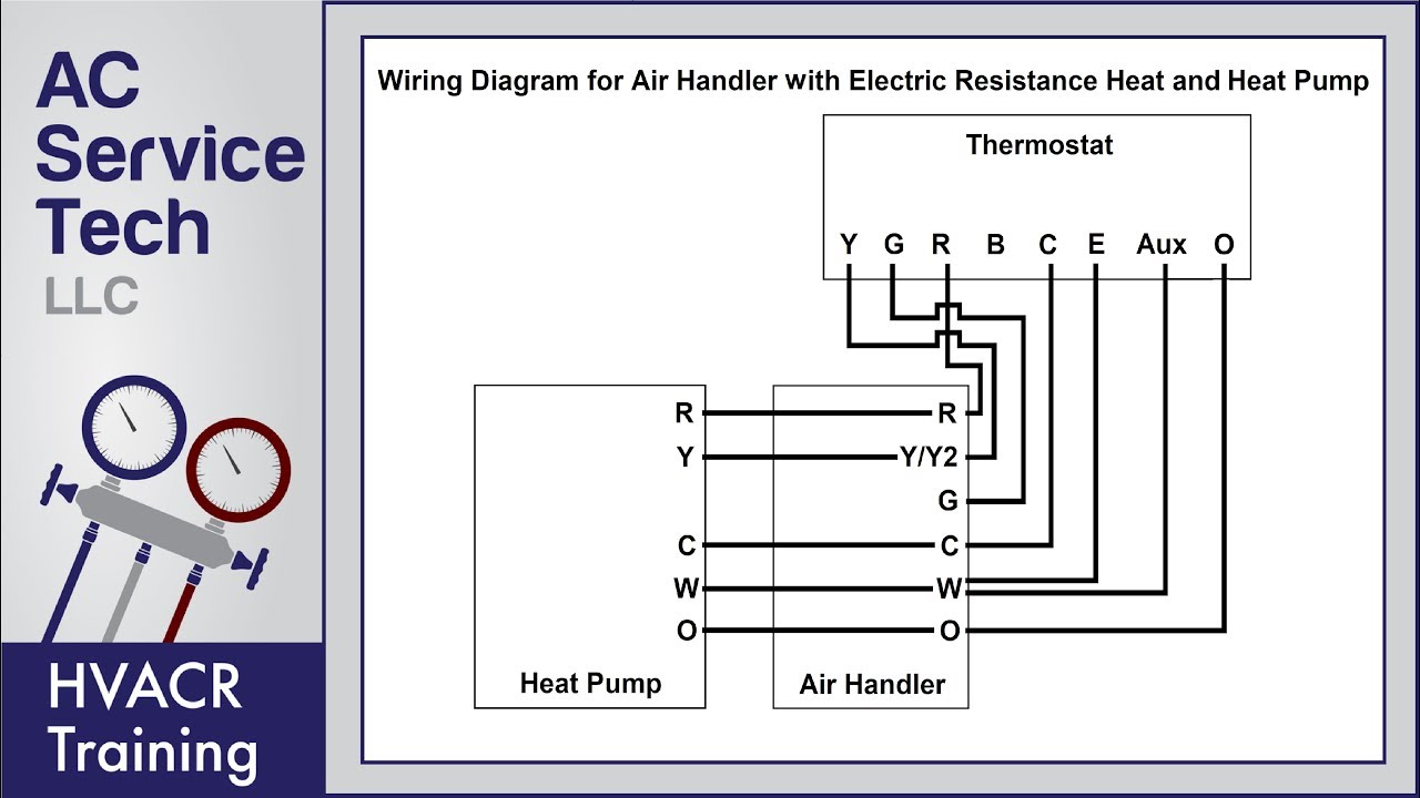
Air handler heat pump electric resistance. One is for cool and the other is for heat, hence the abbreviation “rh” and “rc”. Apr 21, i purchased one of these honeywell rthb thermostats to try it out, but the instructions are pretty much useless and my wires coming out of.
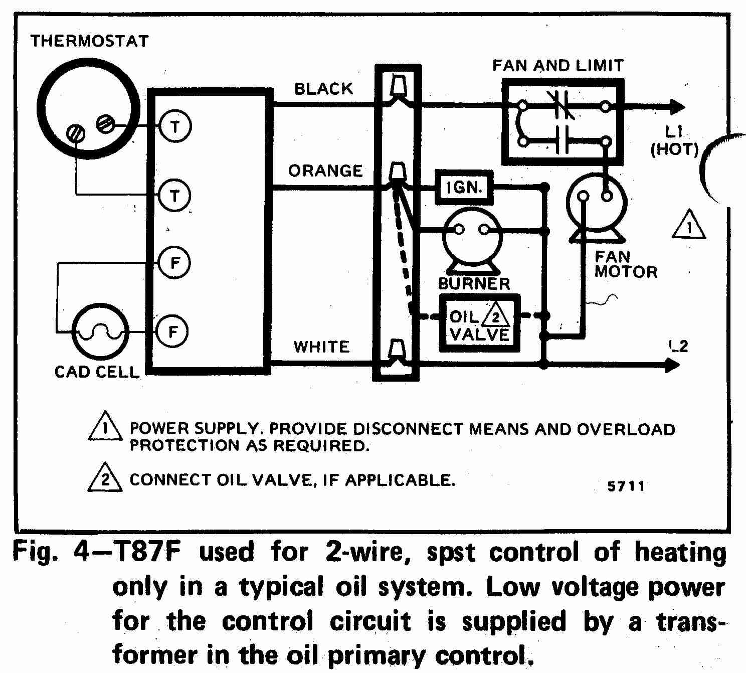
If your thermostat controls your heat, you will have a white wire. The yellow wire connects to your. Figure 1 is a circuit diagram showing the simplest possible known thermostat control system for heating and cooling operation of an a/c and furnace or a/c and electric heat system.
4 wire honeywell thermostat rth111b wiring diagram wiring diagram is a simplified normal pictorial representation of an electrical circuit. 1 3 4 2 photograph your wiring this is important. The g wire is green and connects to the fan.
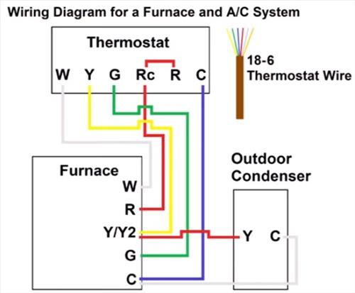
The diagram shows how the wiring works. Basic thermostat wiring for furnace and air conditioner. However your connections may seem a little different on the thermostat itself.
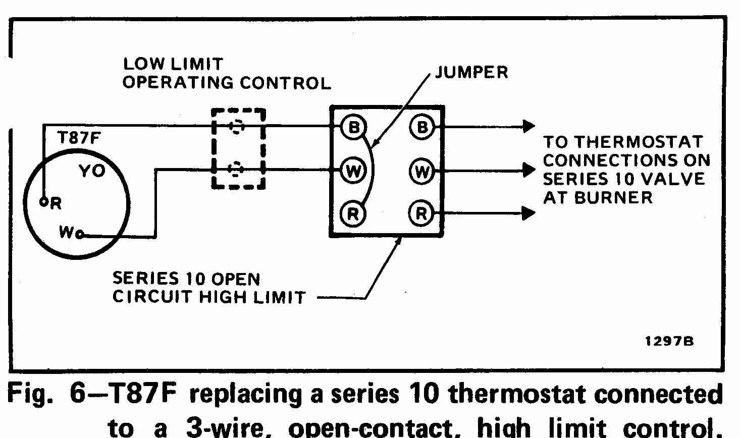
Honeywell 2 wire thermostat wiring diagram heat only. A gas oil or electric furnace 2 or 3 wires a central air conditioner 2 or 3 wires a hot water system steam or gravit y with or without pump 2 wires a millivolt system 2 wires a central heating system with air conditioning 4. The w wire is connected to your heating system.
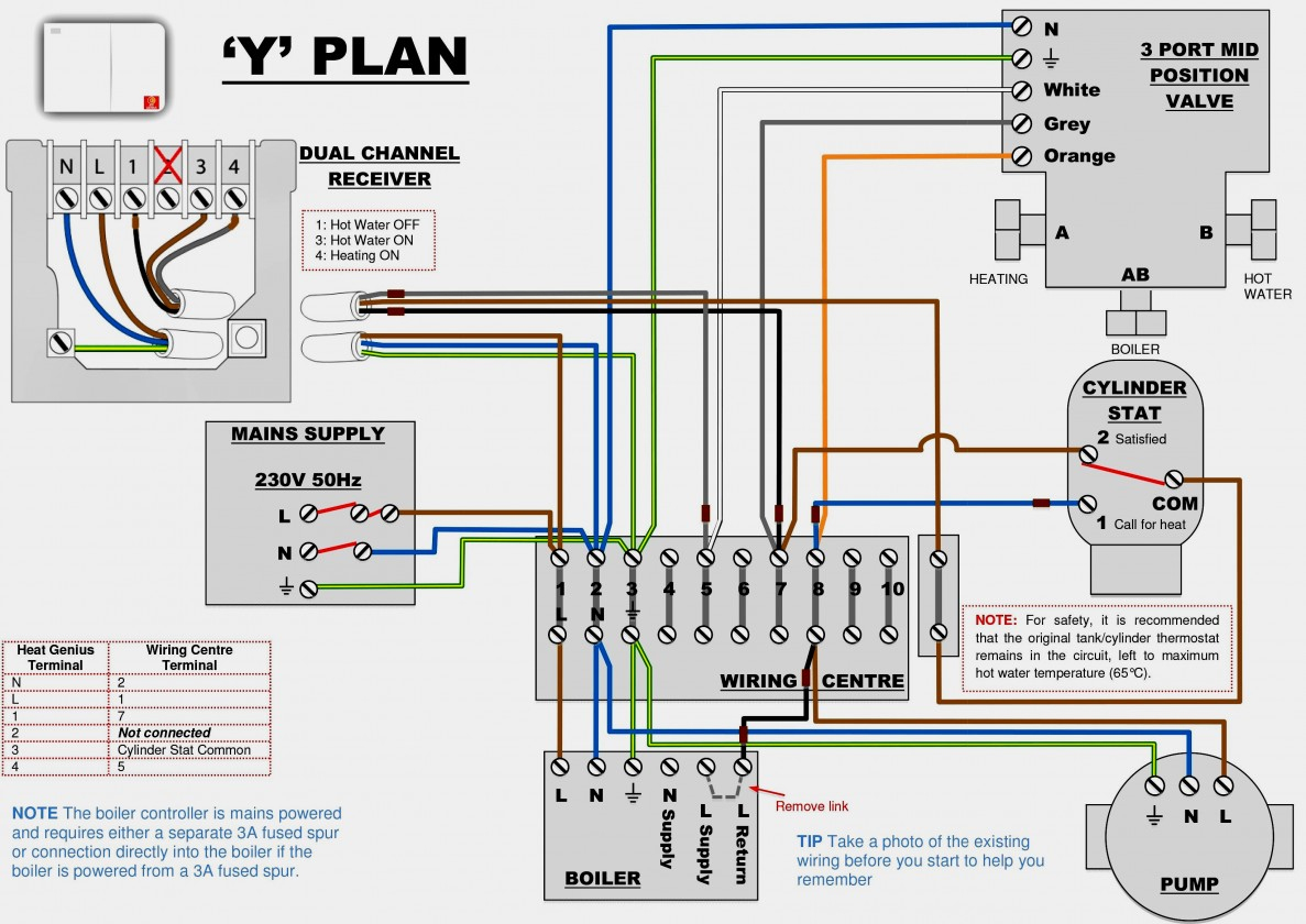
Boiler thermostat wiring diagram from www.flameport.com. Red wire for power (24h). This is the most common configuration f.
The basic heat + a/c system thermostat typically utilizes only 5 terminals. A wiring diagram is a simple visual representation of the physical connections and physical layout of an electrical system or circuit. Furthermore this thermostat wiring diagram is specifically for a system with two transformers your system likely only has one transformer as most typical residential systems only use a single transformer for control.
The thermostat uses 1 wire to control each of your hvac systems primary functions such as heating cooling fan etc. 800 x 600 px, source: When you use your finger or the actual circuit along with your eyes, it may be easy to mistrace the circuit.
Learn how to wire basic thermostats and digital thermostats to operate heat and cooling. The y wire is yellow and connects to your air conditioning compressor. A single trick that we use is to print out a similar wiring diagram off twice.
According to earlier the lines in a 2 wire thermostat wiring diagram heat only represents wires. Air conditioning ac contactor control board 1 this diagram is to be used as reference for the low. The red wire or 24 vac power lead is connected straight to the rc 4 terminals.
It shows how the electrical wires are interconnected and can also show where fixtures and components may be connected to the system. For this system, you will notice that g (air handler R the r terminal is the power.
The 18 refers to the gauge and the 5 refers to how many individual wires are inside the cable. See the diagram below for what each wire controls on your system: 2 wire thermostat wiring furnaces the most basic thermostat has 2 wires.
The thermostat uses 1 wire to control each of your hvac system’s primary functions, such as heating, cooling, fan, etc. Furthermore, this thermostat wiring diagram is specifically for a system with two transformers. The thermostat controls the operation of the heater, compressor and blower as shown in figure 1.
The basic heat + a/c system thermostat typically utilizes only 5 terminals. Print the wiring diagram off and use highlighters to be able to trace the signal. Two wire thermostat wiring is used for furnaces only and usually doesn’t need a “c” or “common” wire.
Green the green wire connects to the fan. I show where the wires go at the thermostat, the color code, then down at the furnace control board,.
Room Thermostat Wiring Diagrams For Hvac Systems Hvac Thermostat Wiring Diagram Cadician's Blog
5 Wire Thermostat Wiring Diagram Wiring Diagram
Thermostat Wiring Diagrams! 10 Most Common! YouTube
Thermostat Signals And Wiring Wiring Diagram For Thermostats Cadician's Blog
Thermostat Wiring Diagram 2 Wire Fantastic Honeywell Thermostat Wiring Diagram 2 Wire

HVAC Technician Training Step 10 Thermostat Basic Functions Freedom Heating & Air

Wiring A Thermostat To A Furnace
Thermostat wiring question (HVAC has 7 wires) Ask the Community Wyze Community

White Rodgers Thermostat Wiring Diagram 1F79 Nice Emerson Thermostat Wiring Diagram P150

Thermostat Wiring Explained

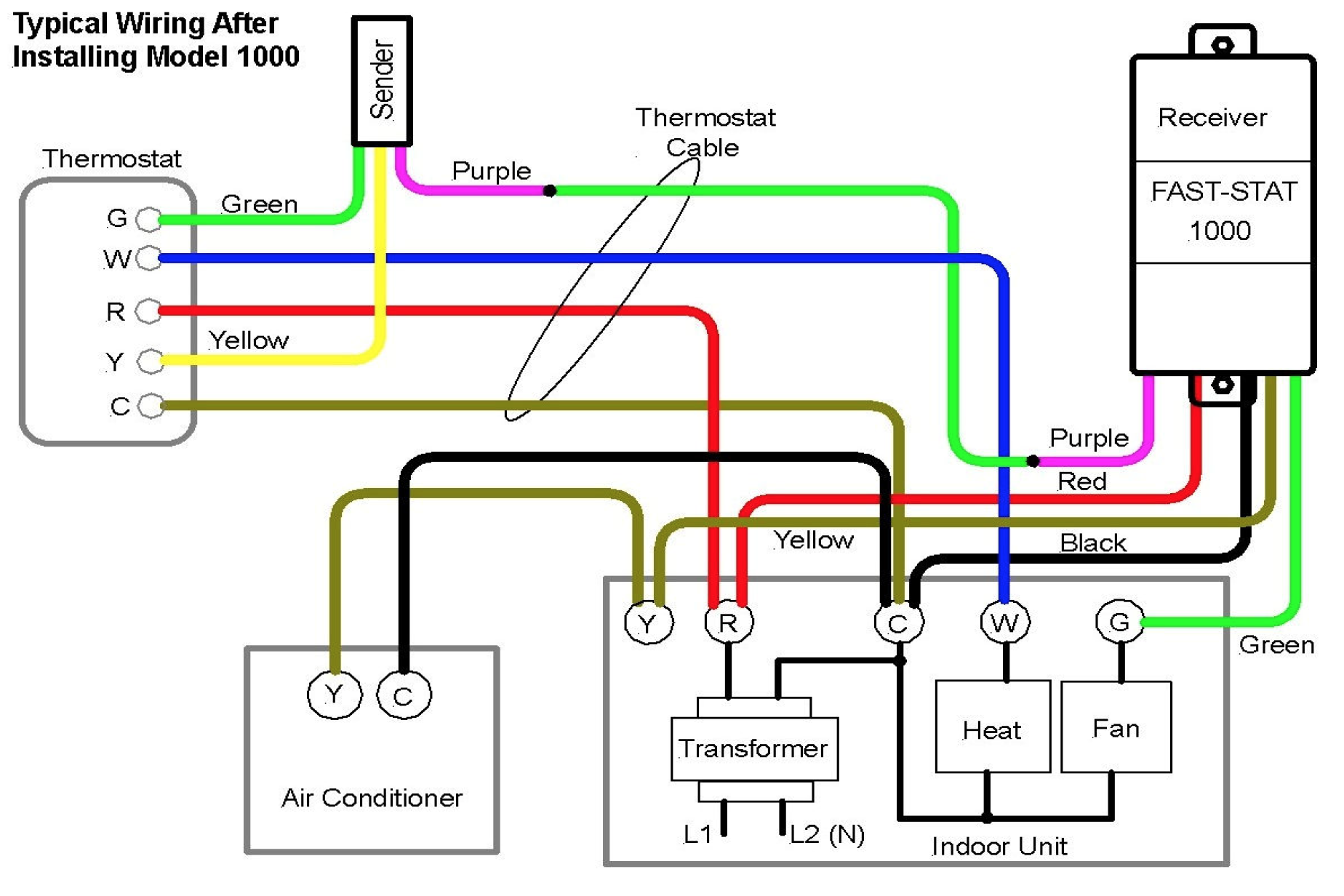
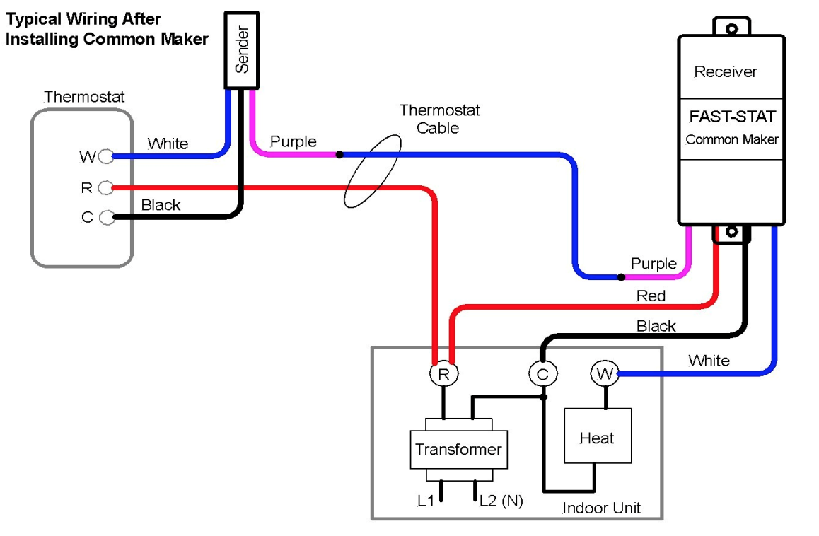
FastStat 1000 and Common Maker Installation Guide Simple
3 Wire Thermostat Wiring Diagram Simple Room Thermostat Wiring Diagrams, Hvac Systems

5 Wire Thermostat Wiring Diagram — UNTPIKAPPS

Honeywell Rth6360 Thermostat Wiring Diagram
How to Wire a Thermostat Explained with Diagram
Simple Wiring Diagram Page 506 Omnicelusa 5 Wire Thermostat Wiring Diagram Wiring Diagram
Basic Thermostat Wiring Diagram Collection Wiring Diagram Sample

Two Wire Thermostat Wiring Diagram
Collection Of Heating and Cooling thermostat Wiring Diagram Download
